System Setup
This document will show you how to get started with the Tria Wideband mmWave Radio Development Platform for RFSoC Gen-3. Follow the step-by-step instructions to assemble the platform, setup your computer, and use RFSoC Explorer® in MATLAB to configure the Otava DTRX2 Dual Transceiver mmWave Radio Card, generate and acquire signals.
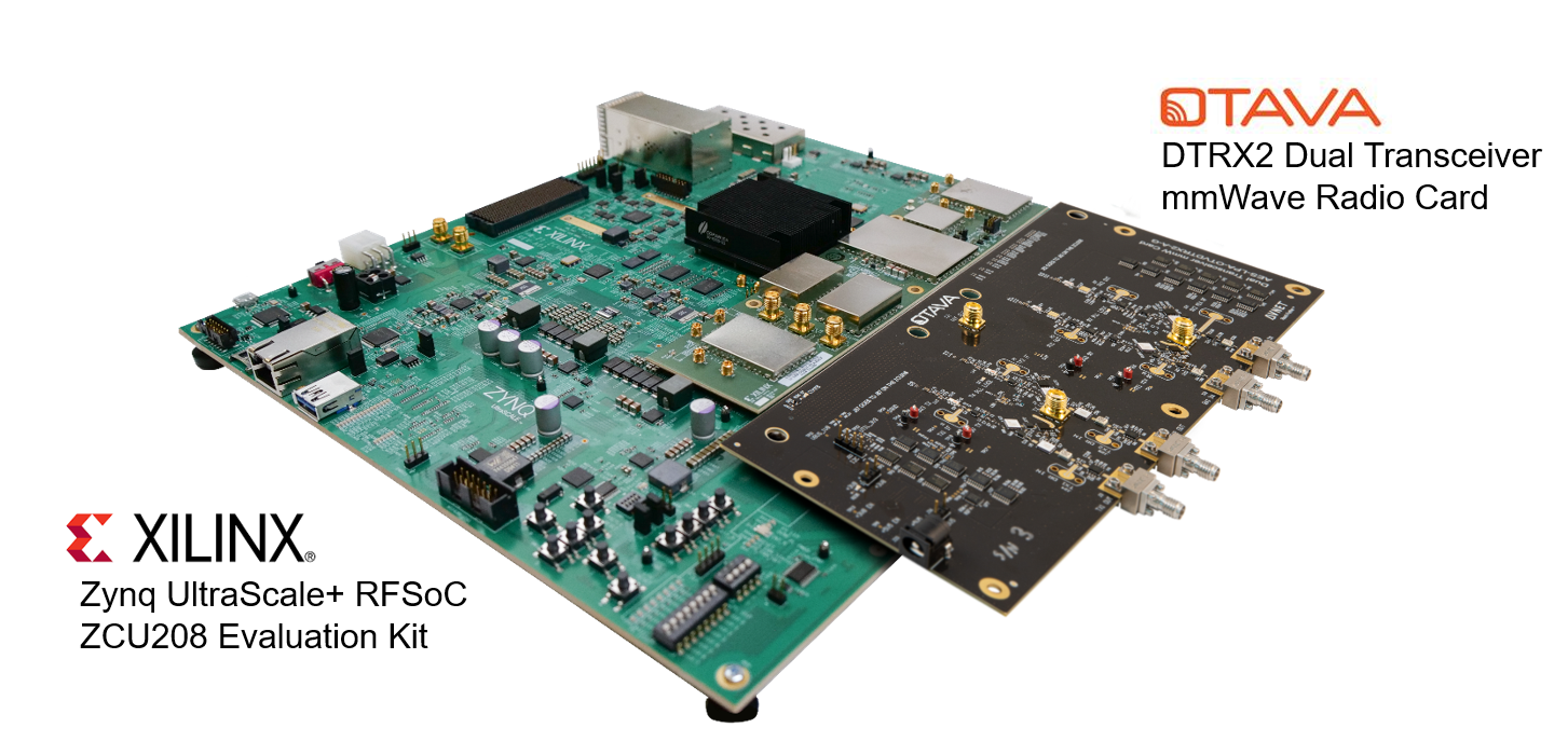
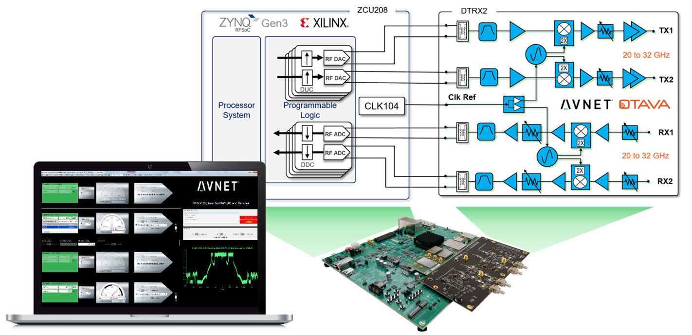
Platform Overview
The Tria Wideband mmWave Radio Development Platform for RFSoC Gen-3 is ideal for prototyping RF applications in mmW bands including 5G NR FR2, wireless backhaul, as well as K/Ka band radar and SATCOM. This platform combines the Otava DTRX2 Dual Transceiver mmWave Radio Card — jointly developed by Otava and Tria — with the AMD Zynq™ UltraScale+™ RFSoC ZCU208 Evaluation Kit.
Warning
This platform can radiate radio frequency energy and has not been tested for CE, FCC, or IC compliance. The intended use is for demonstration, engineering development, or evaluation purposes. See Regulatory Compliance Information
Platform Components
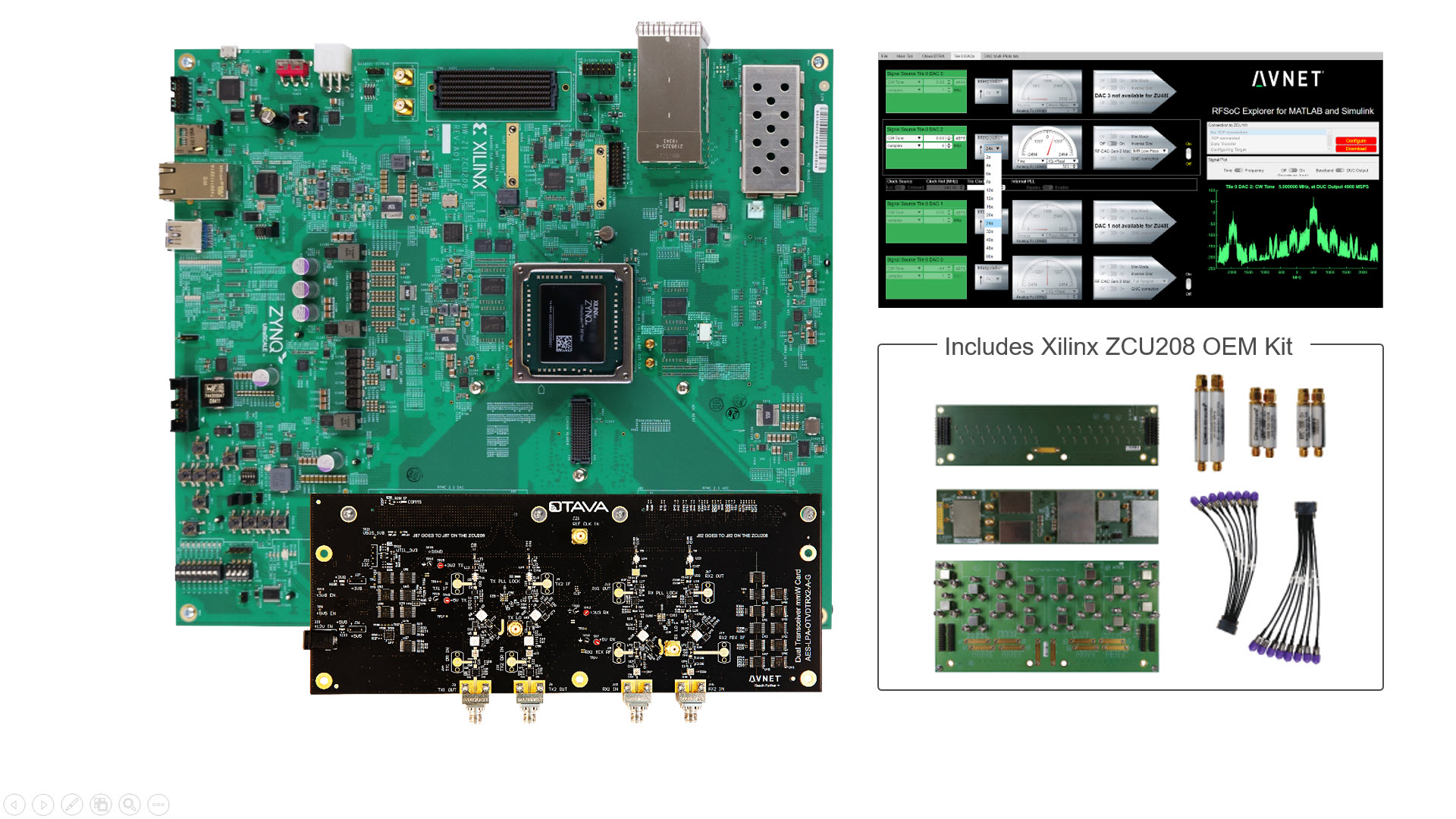
Required Equipment
In addition to the mmWave platform, you will need the following.
Laptop or PC running Windows 10 OS
Bench power supply for 12V, 2Amps min
40GHz Spectrum analyzer for Transmitter tests
40GHz Signal generator for Receiver tests
1x or more RF coaxial cables (2.92mm to 2.92 or 2.4mm on test equipment)
3x 2.92mm male 50-ohm terminations (rated for 40GHz, 0.5W or higher)
1x RF SMA coax cable to connect the CLK104 Reference Clock (in the ZCU208 kit)
1x 10dB SMA coaxial attenuator or low-pass filter (for DTRX2 Ref clock input port)
Optional – n258, n257, n260 band-pass filters
12V jack to banana plug DC electrical wires (in the Otava DTRX2 kit)
Install RFSoC Explorer
RFSoC Explorer provides native connection to MATLAB® and Simulink®, featuring graphical control of the platform and intuitive APIs for programmatic access.
Your computer will need the following MathWorks software.
MATLAB (supported versions)
DSP System Toolbox
Fixed-Point Designer
Communications Toolbox
Signal Processing Toolbox
Install one of the following support packages from the MATLAB Add-On Manager
HDL Coder Support Package for Xilinx FPGA and SoC Devices
SoC Blockset Support Package for Xilinx Devices
SoC Blockset Support Package for AMD FPGA and SoC Devices
Optional toolboxes for working with standards-compliant waveforms in RFSoC Explorer
LTE Toolbox (optional)
5G Toolbox (optional)
Get a Free MATLAB Trial Package for RFSoC
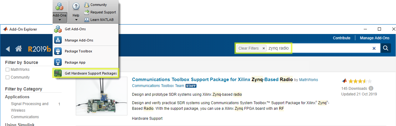
RFSoC Explorer installs easily using the MATLAB Add-Ons store.
From MATLAB > Add-Ons, search for RFSoC Explorer and click install
From MATLAB > Add-Ons, search for Communications Toolbox Support Package for Xilinx Zynq-Based Radio and click install
If prompted, click Setup Later
Hardware Setup
The AMD ZCU208 Evaluation Kit has many jumpers and switches that are shipped with default states, which do not need to change for this tutorial. In the following steps we describe the minimal configuration. For a comprehensive setup guide, refer to the ZCU208 Software Install and Board Setup
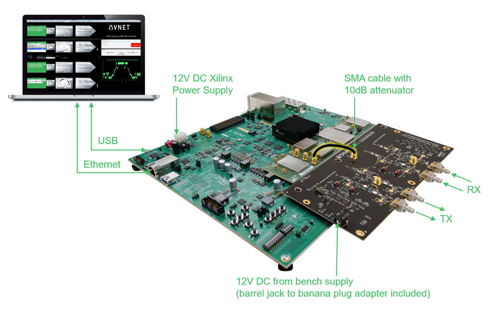
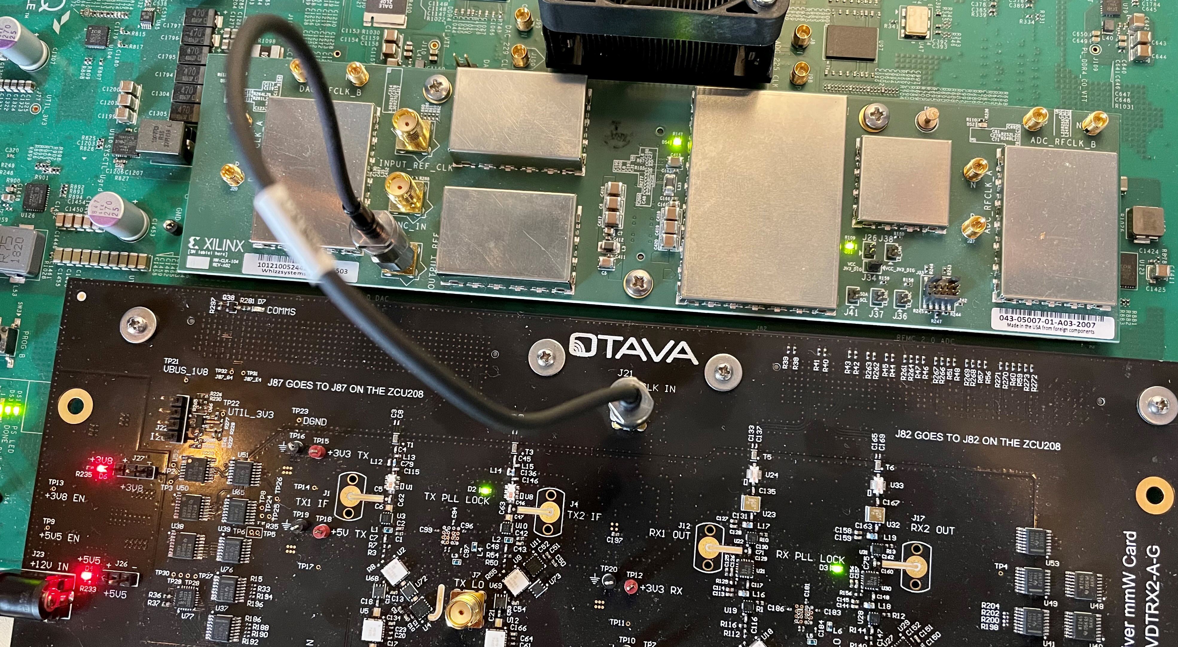
Refer to the diagram above when making the following connections.
Connect the AMD CLK104 module to the ZCU208 with the included screws
Connect the Otava DTRX2 mmWave Card to the ZCU208 with the included screws
Connect the ZCU208 to your PC with Ethernet and USB cables. USB is optional for terminal access to Linux running on the board.
DO NOT CONNECT POWER TO THE DTRX2 CARD (this will be done later)
Use one of the provided SMA cables from the ZCU208 kit to connect CLK104 OUTPUT_REF (J10) to DTRX2 REF CLK IN (J21).
Note
For reference clock spurious mitigation, we recommend a 10dB coaxial attenuator, or a low-pass filter (with >122.88MHz cutoff) between the CLK104 output and the REF_CLK_IN input on the DTRX2 card
Connect DTRX2 RF inputs/outputs to test equipment using 2.92mm mmW coaxial cables
TX outputs @ J3 (Ch1) and J6 (Ch2)
RX inputs @ J10 (Ch1) and J15 (Ch2)
Warning
All unused RF channels input/output connectors on the DTRX2 radio card must be terminated with 50 ohms 2.92mm terminations.
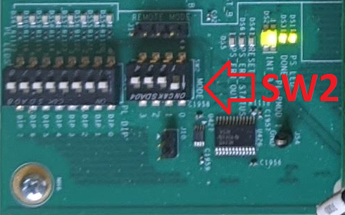
Set ZCU208 to boot from the SD card by setting (SW6) switches as shown below
Prepare SD Card
Follow these steps to load a custom SD card boot image for the ZCU208, allowing it to control the Otava DTRX2 card via RFSoC Explorer.
Remove the SD card from the ZCU208, insert into your PC, and format as FAT using a tool like SD Memory Card Formatter
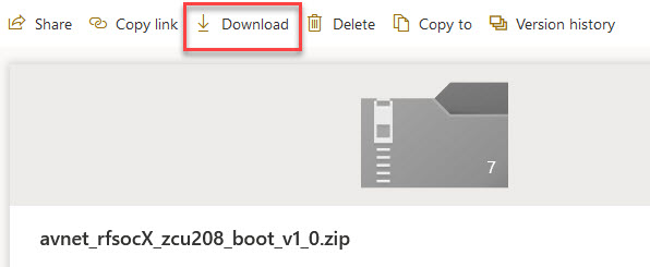
Use one of the links below to download the SD boot image archive.
RFSoC Explorer v2.2.0 and earlier
ZCU208 ES1 SD Card Image - avnet_rfsocX_zcu208es1_boot_v1_0.zip
ZCU208 Production SD Card Image - avnet_rfsocX_zcu208_boot_v1_0.zip
RFSoC Explorer v2.3.0 and later
ZCU208 ES1 SD Card Image - avnet_rfsocX_zcu208es1_boot_v1_1.zip
ZCU208 Production SD Card Image - avnet_rfsocX_zcu208_boot_v1_1.zip
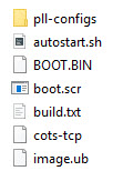
Unzip the archive to the root level of the SD card
Safely eject the SD card from the PC and replace in the ZCU208
Note
Design File Information The software and firmware contained in the SD Card image are biult upon the AMD RF Data Converter Evaluation Tool (v2020.2). Our customizations are accomplished via TCL scripts for the AMD Vivado project, and several modifications to the AMD PetaLinux BSP. The source code for these modifications is freely available. We are in the process of moving our private GitHub repo to public status so that the project can be cloned/forked/etc.
Boot & Network Configuration
The default way to connect to the board is by setting a static IP address on your host PC. We also include instructions for connecting the board to a networked router and allowing the board to use DHCP to obtain an IP address.
DHCP IP (default)
Use this method when connecting the ZCU208 to your PC using a network (via Ethernet router for instance). You will need a USB cable connected to the mini-USB port on the ZCU208 board and your PC.
Open a serial terminal emulator (e.g. TeraTerm) on your PC.
Note
For help installing the ZCU208 USB-UART driver and setting up a serial terminal emulator, consult ZCU208 Software Install and Board Setup
Turn the ZCU208 power switch ON (near the 12V connector)
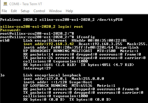
Login into the ZCU208 as
login: root Password: rootDiscover the board IP address using the command
ifconfig. Take note of this IP address You will use it in the next section to connect RFSoC Explorer.
Static IP
Use this method when connecting the ZCU208 directly to your PC.
Ensure that the ZCU208 power switch is OFF (near the 12V connector)
Remove the SD card from the ZCU208 and insert into your PC
Open the autostart.sh file in a test editor. Set
USE_DHCP=false
# Set true if your network assigns an IP address via DHCP
# Set false for static IP address
USE_DHCP=false
Safely eject the SD card from the PC and replace into ZCU208
Turn the ZCU208 power switch ON
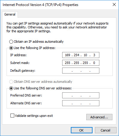
The application auto-start function creates an IP connection for the board at address 169.254.10.2 To use a different IP address, simply modify the
IPADDRfield in the autostart.sh file.
# Static IP address (you can set to this to whatever works for you)
IPADDR="169.254.10.2"
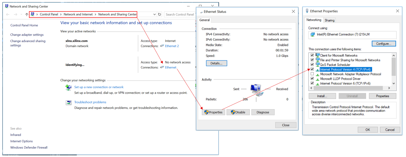
Set a static IP for your host PC’s Local Ethernet adapter. Make sure your PC and the board are on the same subnet and gateway. See example below
Start RFSoC Explorer
Start application in MATLAB with the following API command:
>> RFSoC_Explorer('startup')
Select “ZCU208 + Otava DTRX2 mmWave RF Front-end” from the board menu:

Note
The board can be selected using the API RFSoC_Explorer('startup','board_id',4)
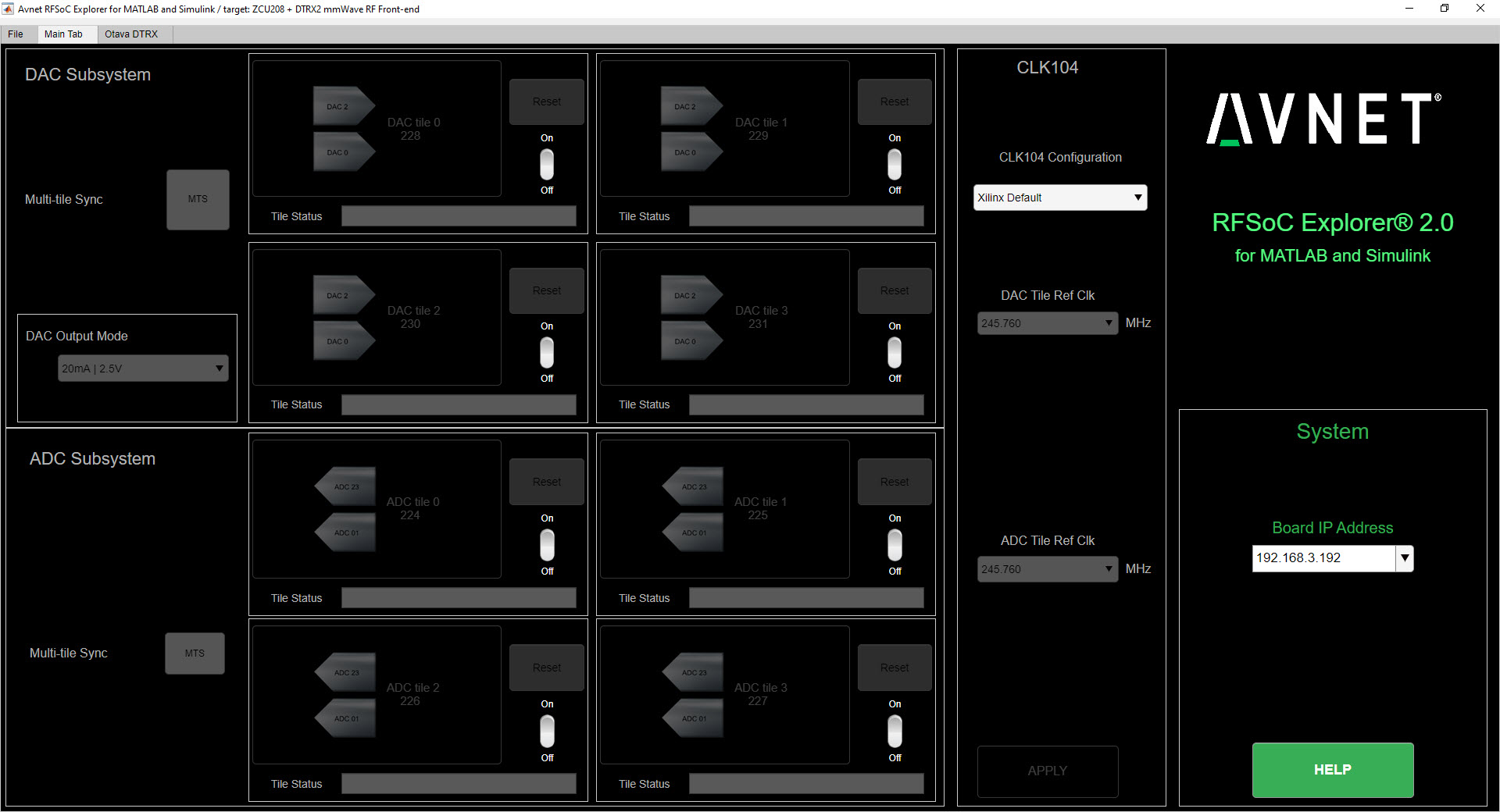
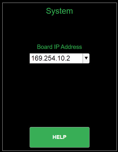
On the Main tab, under “System”, enter the IP address of the ZCU208. The default board addess is: 169.254.10.2.
Note
You may need to maximize the RFSoC Explorer window to reveal the IP Address dropdown
If a successful TCP/IP connection is established with the board, the IP address turns from black to red, and the address is stored in the dropdown menu.
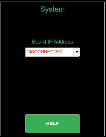
If a TCP/IP connection cannot be established with the board, the app reports “DISCONNECTED” in red.
RFSoC Explorer - ADC/DAC Memory Considerations
The RFSoC Programmable Logic (PL) design implemented on the ZCU208 imposes a few constraints on the DAC replay waveform and the ADC capture buffer.
RF-DAC
BRAM can play unique waveforms to each channel in a tile
PL-DDR is single broadcast. User selects which RF-DAC tiles receive the waveform
PL-DDR can broadcast to multiple tiles while other tiles use BRAM
RF-ADC
BRAM mode: tiles captured simultaneously
BRAM captures occur at full rate
User selects which tiles are streamed to PL-DDR
PL-DDR captures occur sequentially
DDR captures are limited to Fsbb = 2.25 GSPS
PL-DDR mode in dual ADC architectures renders Real Mode unavailable
Configure System Reference Clocks
The CLK104 module provides an ultra low-noise, wideband RF clock source for the ZCU208 RF-ADCs and RF-DACs. We use the RFSoC Explorer to configure CLK104 to ouptut a coherent 122.88MHz reference for the DTRX2 LO PLLs. For more information refer to AMD UG1437 - CLK104 RF Clock Add-onCard
The following picture shows the details of the CLK104 module. The bottom SMA is the 122.88MHz reference clock output to be connected to the DTRX2 input reference clock port. And the other SMA connector above, labelled “INPUT_REF_CLK” is a provision for an external 10MHz master reference clock signal (used for synchronization with test equipments for instance). When an external 10MHz is not provided, the CLK104 module needs to be configured to use the internal 10MHz TCXO, as decribed in the steps below.
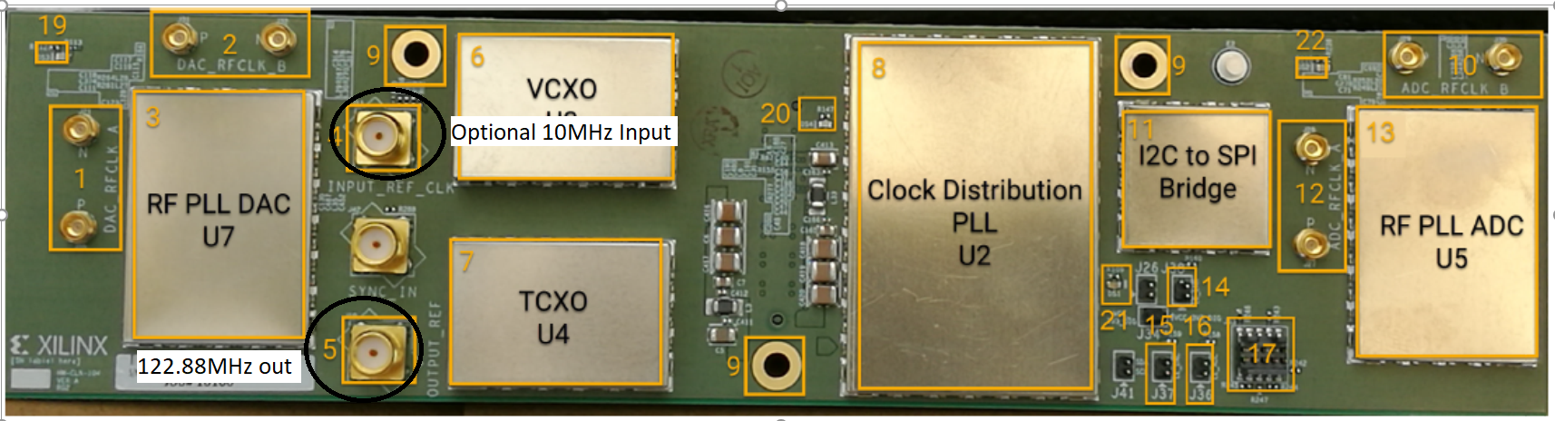
AMD CLK104 System Clock Module
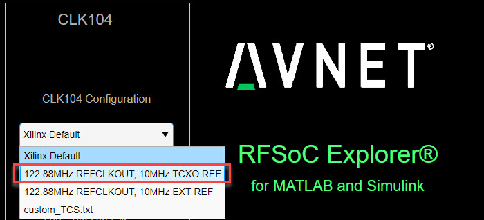
Go to the RFSoC Explorer Main tab
Select CLK104 Configuration > 122.88MHz REFCLKOUT_10MHz TCXO REF
Note
The 122.88MHz REFCLKOUT_10MHz TCXO REF configuration points to the register configuration file for the LMK04828 clock distribution chip on the CLK104 module. This particular file sets the LMK04828 to take the on-board 10MHz TCXO for reference clock signal. If you wish to synchronize the setup to a test instrument 10MHz output reference, connect this port from the back of the instrument to the CLK104 SMA labelled “INPUT_REF_CLK” (direct connection and no attenuator needed) and use the 122.88MHz REFCLKOUT_10MHz EXT REF configuration (typically recommended for demodulation and for EVM measurements). On the other end, for best EVM performance, and because of the limited amplitude level out of J10 on the CLK104 module, consider driving the DTRX2 card reference clock port directly with a clean CW external source set at 122.88MHz and about +15dBm amplitude. Finally, the tool also allows for a custom LMK04828 configuration file to be loaded into the CLK104 module. The file must be created using the Texas Instruments TICSPRO utility, saved as TEXT format, filename custom_TCS.txt, and located in the same directory as the RFSOC Explorer app.
Power Up DTRX2
Connect your test equipment to the DTRX2 RF and TX ports
Terminate unused channels with a 2.92mm 50 ohms termination
Apply 12V DC power to the DTRX2 card, using the DC barrel jack-to-banana plugs cable provided.
Both D4 and D6 “Power Good” red LEDs should be ON. The idle current drawn from the 12V supply should be about 45mA.
It is recommended to set the current limit of the 12V power supply to 2 amps if running both transmit and receive channels simulateously. Please refer to the datasheet for information as to the specific current draw in either transmit or receive mode.
In the next sections you will power up the TX and RX signal chains using RFSoC Explorer and observe the green RX PLL LOCK and TX PLL LOCK LEDs turn ON, as shown in this image.
Click NEXT to setup the DTRX2 transmit chains.